
可视云物联网太阳能智能控制器英文说明书
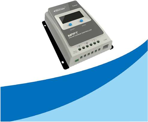
 Keshiyu-AN Series
——MPPT Solar Charge Controller
User Manual
Models:
Keshiyu1206AN/Keshiyu2206AN
Keshiyu1210AN/Keshiyu2210AN
Keshiyu3210AN/Keshiyu4210A
Important Safety Instructions
Please save this manual for future review.
This manual contains safety, installation and operation for Maximum Power Point
Tracking (MPPT) Keshiyu AN series controller ("the controller" as referred to in this
manual).
General Safety Information
Read carefully all the instructions and warnings in the manual before installation.
No user serviceable components inside the controller. DO NOT disassemble or
attempt to repair the controller.
Mount the controller indoors. Prevent exposure to the elements and do not allow
water to enter the controller.
Install the controller in a well ventilated -place. The controller’s heat sink may
become very hot during operation.
It is suggested to install appropriate external fuses/breakers.
Make sure to switch off all PV array connections and the battery fuse/breakers
before controller installation and adjustment.
Power connections must remain tight to avoid excessive heating from loose
connection.
CONTENTS
1. General Information........................................................................1
1.1 Overview..............................................1
1.2 Characteristics.........................................2
1.3 Designations of Controller Models ........................3
1.4 Maximum Power Point Tracking Technology ...............3
1.5 Battery Charging Stage .................................4
2. Installation Instructions .................................................................7
2.1 General Installation Notes ...............................7
2.2 PV Array Requirements .................................7
2.3 Wire Size ............................................10
2.4 Mounting.............................................11
3. Operation.......................................................................................14
3.1 Button ...............................................14
3.2 Interface .............................................14
3.3 Setting...............................................16
3.4 Accessories (optional) .................................21
4. Protections, Troubleshooting and Maintenance........................23
4.1 Protection ............................................23
4.2 Troubleshooting.......................................24
4.3 Maintenance .........................................24
5. Technical Specifications..............................................................26
Annex I Conversion Efficiency Curves ...........................................28
Annex II Dimensions ........................................................................34
1. General Information
1.1 Overview
The Keshiyu AN series. Based on common negative design and advanced MPPT
control algorithm, with LCD displaying running status, this product is artistic,
economical and practical. Improving the MPPT control algorithm further, Keshiyu AN
series can minimize the maximum power point loss rate and loss time, quickly track
the maximum power point of the PV array and obtain the maximum energy from solar
modules under any conditions; and can increase the ratio of energy utilization in the
solar system by 10%-30% compared with a PWM charging method. The limitation
function of the charging power and current and reducing charging power function
automatic improve the stability which works even connecting oversize PV modules
and in high temperature, and increase the professional protection chip for the
communication port, further improving the reliability and meeting the different
application requirements.
With the adaptive three-stage charging mode based on a digital control circuit, Keshiyu
AN series controllers can effectively prolong the life-cycle of batteries, significantly
improve the system performance and support all-around electronic protection
functions, including overcharging and over discharging protection to minimize
damages to components of the system caused by incorrect installation or system
failure at the utmost, and effectively ensure safer and more reliable operation of the
solar power supply system for a longer service time. This modular solar controller can
be widely used for different applications, e.g., Communication base stations,
household systems, and field monitoring, etc.
Features:
• Advanced MPPT technology, with efficiency no less than 99.5%
• Ultra-fast tracking speed and guaranteed tracking efficiency
• Advanced MPPT control algorithm to minimize the maximum power point loss
rate and loss time
• Wide MPP operating voltage range
• High quality components, perfecting system performance, with maximum
conversion efficiency of 98%
• Accurate recognition and tracking of multiple-peaks maximum power point
• International famous brands of ST and IR's components of high quality and low
failure rate are used, which can ensure the product’s service life
• Charging power and current limitation function
• Compatible with lead-acid and lithium-ion batteries
• Battery temperature compensation function
• Real-time energy statistics function
• Overheating power reduction function
• Multiple load work modes
1
 • The communication port adopts professional protection chip, which can provide
5VDC power supply, and has over-current and short-circuit protection.
• With RS-485 communication bus interface and Modbus communication protocol,
it is available to meet various communication requirements in different situations. • Monitor and set the parameters via mobile phone APP or PC software
• Full-load operation without any drop in capacity within the range of working
environment temperature
• Extensive electronic protection
1.2 Characteristics
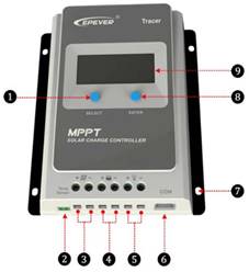
Figure 1 Product Characteristics
❶ SELECT button ❻ RS485 communication interface
❷ RTS★ Interface ❼ Mounting Hole Φ5mm
❸ PV Terminals ❽ ENTER button
❹ Battery Terminals ❾ LCD
❺ Load Terminals
★If the temperature sensor is short-circuited or damaged, the controller will
charge or discharge at the default temperature setting of 25 ºC.
2


 1.3 Designations of Controller Models
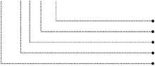
EXAMPLE:
Keshiyu 1 2 10 AN
Common Negative System
Max. PV open circuit voltage 100V
System Voltage12/24VDC
Charge & discharge current10A
Product Series
1.4 Maximum Power Point Tracking Technology
Due to the nonlinear characteristics of solar array, there is a maximum energy output
point (Max Power Point) on its curve. Traditional controllers, with switch charging
technology and PWM charging technology, can’t charge the battery at the maximum
power point, so can’t harvest the maximum energy available from PV array, but the
solar charge controller with Maximum Power Point Tracking (MPPT) Technology can
lock on the point to harvest the maximum energy and deliver it to the battery.
The MPPT algorithm of our company continuously compares and adjusts the
operating points to attempt to locate the maximum power point of the array. The
tracking process is fully automatic and does not need user adjustment.
As the Figure 1-2, the curve is also the characteristic curve of the array, the MPPT
technology will ‘boost’ the battery charge current through tracking the MPP. Assuming
100% conversion efficiency of the solar system, in that way, the following formula is
established:
Input power (PPV)= Output power (PBat)
Input voltage (VMpp) *input current (IPV) =Battery voltage (VBat) *battery current (IBat)
Normally, the VMpp is always higher than VBat, Due to the principle of conservation of
energy, the IBat is always higher than IPV. The greater the discrepancy between VMpp
&VBat, the greater the discrepancy between IPV& IBat. The greater the discrepancy
between array and battery, the bigger reduction of the conversion efficiency of the
system, thus the controller’s conversion efficiency is particularly important in the PV
system.
Figure 1-2 is the maximum power point curve, the shaded area is charging range of
traditional solar charge controller (PWM Charging Mode), it can obviously diagnose
3
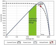
 that the MPPT mode can improve the usage of the solar energy resource. According
to our test, the MPPT controller can raise 20%-30% efficiency compared to the PWM
controller. (Value may be fluctuant due to the influence of the ambient circumstance
and energy loss.)
Figure 1-2 Maximum Power Point Curve
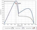
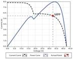
In actual application, as shading from cloud, tree and snow, the panel maybe appear
Multi-MPP, but in actually there is only one real Maximum Power Point. As the below
Figure 1-3 shows:
Figure 1-3 Mutil-MPP Curve
If the program works improperly after appearing Multi-MPP, the system will not work
on the real max power point, which may waste most solar energy resources and
seriously affect the normal operation of the system. The typical MPPT algorithm,
designed by our company, can track the real MPP quickly and accurately, improve the
utilization rate of the array and avoid the waste of resources.
1.5 Battery Charging Stage
The controller has a 3 stages battery charging algorithm (Bulk Charging, Constant
Charging and Float Charging) for rapid, efficient, and safe battery charging.
4
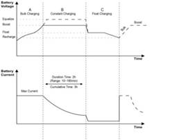

 Figure 1-4 Battery changing stage Curve
A) Bulk Charging
In this stage, the battery voltage has not yet reached constant voltage (Equalize or
Boost Voltage), the controller operates in constant current mode, delivering its
maximum current to the batteries (MPPT Charging).
B) Constant Charging
When the battery voltage reaches the constant voltage setpoint, the controller will
start to operate in constant charging mode, this process is no longer MPPT charging,
and in the meantime the charging current will drop gradually, the process is not the
MPPT charging. The Constant Charging has 2 stages, equalize and boost. These two
stages are not carried out constantly in a full charge process to avoid too much gas
precipitation or overheating of battery.
Boost Charging
The Boost stage maintain 2 hours in default, user can adjust the constant time and
preset value of boost voltage according to demand.
The stage is used to prevent heating and excessive battery gassing.
Equalize Charging
WARNING: Explosive Risk!
Equalizing flooded battery would produce explosive gases, so well
ventilation of battery box is recommended.
CAUTION: Equipment damage!
Equalization may increase battery voltage to the level that damages
sensitive DC loads. Verify that all load allowable input voltages are 11%
greater than the equalizing charging set point voltage.
5
 CAUTION: Equipment damage!
Over-charging and excessive gas precipitation may damage the battery
plates and activate material shedding on them. Too high an equalizing
charge or for too long may cause damage.
Please carefully review the specific requirements of the battery used in the system.
Some types of batteries benefit from equalizing charge on a regular basis, which is
able to stir electrolyte, balance battery voltage and accomplish chemical reaction.
Equalizing charge increases battery voltage, higher than the standard complement
voltage, which gasifies the battery electrolyte.
The controller will equalize the battery on 28th each month. The constant equalization
period is 0~180 minutes. If the equalization isn’t accomplished in one-time, the
equalization recharge time will be accumulated until the set time is finished. Equalize
charge and boost charge are not carried out constantly in a full charge process to
avoid too much gas precipitation or overheating of battery.
NOTE:
1) Due to the influence of ambient circumstance or load working, the battery
voltage can’t be steady in constant voltage, controller will accumulate and
calculate the time of constant voltage working. When the accumulated time
reach to 3 hours, the charging mode will turn to Float Charging.
2) If the controller time is not adjusted, the controller will equalize charge
battery once every month following the inner time.
C) Float Charging
After the Constant voltage stage, the controller will reduce charging current to Float
Voltage setpoint. This stage will have no more chemical reactions and all the charge
current transforms into heat and gas at this time. Then the controller reduces the
voltage to the floating stage, charging with a smaller voltage and current. It will reduce
the temperature of the battery and prevent the gassing and charging the battery
slightly at the same time. The purpose of Float stage is to offset the power
consumption caused by self consumption and small loads in the whole system, while
maintaining full battery storage capacity.
In Float charging stage, loads are able to obtain almost all power from solar panel. If
loads exceed the power, the controller will no longer be able to maintain battery
voltage in Float charging stage. If the battery voltage remains below the Recharge
Voltage, the system will leave Float charging stage and return to Bulk charging stage.
6
2. Installation Instructions
2.1 General Installation Notes
Please read the entire installation instructions to get familiar with the installation
steps before installation.
Be very careful when installing the batteries, especially flooded lead-acid battery.
Please wear eye protection, and have fresh water available to wash and clean any
contact with battery acid.
Keep the battery away from any metal objects, which may cause short circuit of the
battery.
Explosive battery gases may come out from the battery during charging, so make
sure ventilation condition is good.
Ventilation is highly recommended if mounted in an enclosure. Never install the
controller in a sealed enclosure with flooded batteries! Battery fumes from vented
batteries will corrode and destroy the controller circuits.
Loose power connections and corroded wires may result in high heat that can melt
wire insulation, burn surrounding materials, or even cause fire. Ensure tight
connections and use cable clamps to secure cables and prevent them from swaying
in mobile applications.
Lead-acid battery and lithium battery are recommended, other kinds please refer to
the battery manufacturer.
Battery connection may be wired to one battery or a bank of batteries. The following
instructions refer to a singular battery, but it is implied that the battery connection
can be made to either one battery or a group of batteries in a battery bank.
Multiple same models of controllers can be installed in parallel on the same battery
bank to achieve higher charging current. Each controller must have its own solar
module(s).
Select the system cables according to 5A/mm2 or less current density in accordance
with Article 690 of the National Electrical Code, NFPA 70.
2.2 PV Array Requirements
(1) Serial connection (string) of PV modules
As the core component of PV system, controller could be suitable for various types of
PV modules and maximize converting solar energy into electrical energy. According to
the open circuit voltage (Voc) and the maximum power point voltage (VMpp) of the
MPPT controller, the series number of different types PV modules can be calculated.
The below table is for reference only.
7
 Keshiyu1206/2206AN:
System voltage | 36 cell 48 cell 54 cell 60 cell Voc<23V Voc<31V Voc<34V Voc<38V Max. Best Max. Best Max. Best Max. Best |
12V 2 2 1 1 1 1 1 1
24V 2 2 - - - - - -
72 cell Voc<46V 96 cell Voc<62V Thin-Film
System
Module
voltage
Max. Best Max. Best
Voc>80V
12V 1 1 - - -
24V 1 1 - - -
NOTE: The above parameter values are calculated under standard test conditions
(STC (Standard Test Condition):Irradiance 1000W/m2,Module Temperature 25℃,
Air Mass1.5.)
Keshiyu1210/2210/3210/4210AN:
System voltage | 36 cell 48 cell 54 cell 60 cell Voc<23V Voc<31V Voc<34V Voc<38V Max. Best Max. Best Max. Best Max. Best |
12V 4 2 2 1 2 1 2 1
24V 4 3 2 2 2 2 2 2
72 cell Voc<46V 96 cell Voc<62V Thin-Film
System
Module
voltage
Max. Best Max. Best
Voc>80V
12V 2 1 1 1 1
24V 2 1 1 1 1
NOTE: The above parameter values are calculated under standard test conditions
(STC (Standard Test Condition):Irradiance 1000W/m2,Module Temperature 25℃,
Air Mass1.5.)
(2) Maximum PV array power
The MPPT controller has the function of current/power-limiting, that is, during the
charging process, when the charging current or power exceeds the rated charging
current or power, the controller will automatically limit the charging current or power to
the rated charging current or power, which can effectively protect the charging parts of
controller, and prevent damages to the controller due to the connection of some
over-specification PV modules. The actual operation of PV array is as follows:
Condition 1:
Actual charging power of PV array ≤ Rated charging power of controller
Condition 2:
Actual charging current of PV array ≤ Rated charging current of controller
8
When the controller operates under “Condition 1”or“Condition 2”, it will carry out the
charging as per the actual current or power; at this time, the controller can work at the
maximum power point of PV array.
WARNING: When the power of PV is not greater than the rated charging
power, but the maximum open-circuit voltage of PV array is more than
50(Keshiyu**06AN)/96V(Keshiyu**10AN) (at the lowest environmental
temperature), the controller may be damaged.
Condition 3:
Actual charging power of PV array>Rated charging power of controller
Condition 4:
Actual charging current of PV array>Rated charging current of controller
When the controller operates under “Condition 3”or“Condition 4”,it will carry out the charging as per the rated current or power.
WARNING: When the power of PV module is greater than the rated
charging power, and the maximum open-circuit voltage of PV array is more
than 50(Keshiyu**06AN)/96V(Keshiyu**10AN)(at the lowest environmental
temperature), the controller may be damaged.
According to “Peak Sun Hours diagram”, if the power of PV array exceeds the rated
charging power of controller, then the charging time as per the rated power will be
prolonged, so that more energy can be obtained for charging the battery. However, in
the practical application, the maximum power of PV array shall be not greater than 1.5
x the rated charging power of controller. If the maximum power of PV array exceeds
the rated charging power of controller too much, it will not only cause the waste of PV
modules, but also increase the open-circuit voltage of PV array due to the influence of
environmental temperature, which may make the probability of damage to the
controller rise. Therefore, it is very important to configure the system reasonably. For
the recommended maximum power of PV array for this controller, please refer to the
table below:
Model Rated Charge Rated Charge Current Power Keshiyu1206AN 10A 130W/12V 260W/24V Keshiyu2206AN 20A 260W/12V 520W/24V Keshiyu1210AN 10A 130W/12V 260W/24V Keshiyu2210AN 20A 260W/12V 520W/24V Keshiyu3210AN 30A 390W/12V 780W/24V Keshiyu4210AN 40A 520W/12V 1040W/24V ①At 25℃ environment temperature 9 | Max. PV Array Max. PV open Power circuit voltage 195W/12V ① 390W/24V 46V 390W/12V ② 60V 780W/24V 195W/12V 390W/24V 390W/12V ① 780W/24V 92V 580W/12V ② 100V 1170W/24V 780W/12V 1560W/24V |
②At minimum operating environment temperature
2.3 Wire Size
The wiring and installation methods must conform to all national and local electrical
code requirements.
PV Wire Size
Since PV array output can vary due to the PV module size, connection method or
sunlight angle, the minimum wire size can be calculated by the Isc* of PV array.
Please refer to the value of Isc in the PV module specification. When PV modules
connect in series, the Isc is equal to a PV modules Isc. When PV modules connect in
parallel, the Isc is equal to the sum of the PV module’s Isc. The Isc of the PV array
must not exceed the controller’s maximum PV input current. Please refer to the table
as below:
NOTE: All PV modules in a given array are assumed to be identical. *Isc=short circuit current(amps) Voc=open circuit voltage.
Model Max. PV input current Max. PV wire size*
Keshiyu1206AN
Keshiyu1210AN 10A 4mm
Keshiyu2206AN
2/12AWG
Keshiyu2210AN 20A 6mm
2/10AWG
Keshiyu3210AN 30A 10mm2/8AWG
Keshiyu4210AN 40A 16mm2/6AWG
*These are the maximum wire sizes that will fit the controller terminals.
CAUTION: When the PV modules connect in series, the open circuit
voltage of the PV array must not exceed 46V (Keshiyu**06AN), 92V
(Keshiyu**10AN) at 25℃ environment temperature.
Battery and Load Wire Size
The battery and load wire size must conform to the rated current, the reference size
as below:
Rated Rated
Battery wire Load wire
Model charge discharge
size size
current current Keshiyu1206AN
Keshiyu1210AN 10A 10A 4mm
Keshiyu2206AN
2/12AWG 4mm2/12AWG
Keshiyu2210AN 20A 20A 6mm
2/10AWG 6mm2/10AWG
Keshiyu3210AN 30A 30A 10mm2/8AWG 10mm2/8AWG
Keshiyu4210AN 40A 40A 16mm2/6AWG 16mm2/6AWG
10
CAUTION: The wire size is only for reference. If there is a long distance
between the PV array and the controller or between the controller and the
battery, larger wires can be used to reduce the voltage drop and improve
performance.
CAUTION: For the battery, the recommended wire will be selected
according to the conditions that its terminals are not connected to any
additional inverter.
2.4 Mounting
WARNING: Risk of explosion! Never install the controller in a sealed
enclose with flooded batteries! Do not install in a confined area where
battery gas can accumulate.
WARNING: Risk of electric shock! When wiring the solar modules, the PV
array can produce open circuit voltages in excess of 100V when in
sunlight.
CAUTION:The controller requires at least 150mm of clearance above and
below for proper air flow. Ventilation is highly recommended if mounted in
an enclosure.
Installation Procedure:
Figure 2-1 Mounting
Step 1: Determination of Installation Location and Heat-dissipation Space
Determination of installation location: The controller shall be installed in a place with
sufficient air flow through the radiators of the controller and a minimum clearance of
11
150 mm from the upper and lower edges of the controller to ensure natural thermal
convection. Please see Figure 2-1: Mounting
CAUTION: If the controller is to be installed in an enclosed box, it is
important to ensure reliable heat dissipation through the box.
Figure 2-2 Schematic of wiring diagram
Step 2:Connect the system in the order of ❶battery ❷ load ❸PV array in
accordance with Figure 2-2,”Schematic Wiring Diagram” and disconnect the system in
the reverse order❸❷❶.
CAUTION: While wiring the controller do not close the circuit breaker or
fuse and make sure that the leads of "+" and "-" poles are connected
correctly.
CAUTION: A fuse which current is 1.25 to 2 times the rated current of the
controller, must be installed on the battery side with a distance from the
battery not greater than 150 mm.
CAUTION: If the controller is to be used in an area with frequent lightning
strikes or unattended area, it must be installed an external surge arrester.
CAUTION: If an inverter is to be connected to the system, connect the inverter directly to the battery, not to the load side of the controller.
Step 3:Grounding
Keshiyu AN series is a common-negative controller, where all the negative terminals of
PV array, battery and load can be grounded simultaneously or any one of them will be
grounded. However, according to the practical application, all the negative terminals
12
of PV array, battery and load can also be ungrounded, but the grounding terminal on
its shell must be grounded, which may effectively shield the electromagnetic
interference from the outside, and prevent some electric shock to human body due to
the electrification of the shell.
CAUTION: For common-negative system, such as motorhome, it is
recommended to use a common-negative controller; but if in the
common-negative system, some common-positive equipment are used,
and the positive electrode is grounded, the controller may be damaged.
Step 4:Connect accessories
Connect the remote temperature sensor cable (model: RTS300R47K3.81A)
Temperature Sensor | Remote Temperature Sensor Cable (Optional) |
(Model:RT-MF58R47K3.81A) (Model:RTS300R47K3.81A)
Connect one end of the remote temperature sensor cable
to the interface ③ and place the other end close to the battery.
CAUTION: If the remote temperature sensor is not connected to the
controller,, the default setting for battery charging or discharging
temperature is 25 °C without temperature compensation.
Connect the accessories for RS485 communication
Refer to chaper3.3 “Setting”
CAUTION: If the remote temperature sensor is not connected to the
controller,, the default setting for battery charging or discharging
temperature is 25 °C without temperature compensation.
Step 5:Powered on the controller
Closing the battery fuse will switch on the controller. Then check the status of the
battery indicator (the controller is operating normally when the indicator is lit in green).
Close the fuse and circuit breaker of the load and PV array. Then the system will be
operating in the preprogrammed mode.
CAUTION: If the controller is not operating properly or the battery indicator
on the controller shows an abnormality, please refer to 4.2
“Troubleshooting”.
13
3. Operation
3.1 Button
Mode Note
Load ON/OFF In load manual mode, it can turn the load On/Off of the load via
the “ENTER” button.
Clear Fault Press the “ENTER” button.
Browsing Mode Press the “SELECT” button.
Press the “ENTER” button. and hold on 5s to enter the setting mode
Press the “SELECT” button. to set the parameters, Setting Mode
Press the “ENTER” button. to confirm the setting parameters or exit the setting mode automatically after 10s.
3.2 Interface
1) Icon
Item Icon Status
PV array Day
14
Night
No charging
Charging
PV Voltage, Current, Power
Battery capacity, In Charging
Battery
Battery Voltage, Current, Temperature
Battery Type
Load ON
Load
Load OFF
Load Voltage, Current, Load mode
2) Fault Indication
Status Icon Description
Battery over discharged | Battery level shows empty, battery frame blink, fault icon blink | ||||
Battery over voltage | Battery level shows full, battery frame blink, fault icon blink | ||||
Battery over temperature | Battery level shows current value, battery frame blink, fault icon blink | ||||
Load failure Load overload① ,Load short circuit
①When load current reaches1.02-1.05 times 1.05-1.25 times, 1.25-1.35 times and
1.35-1.5 times more than nominal value, controller will automatically turn off loads in
50s, 30s,10s and 2s respectively.
15
3) Browse interface
3.3 Setting
1) Clear the generated energy
Operation:
Step 1: Press the “ENTER” button and hold 5s under the PV power interface and the value is flashing.
Step 2: Press the “ENTER” button to clear the generated energy..
2) Switch the battery temperature unit
Press the “ENTER” button and hold 5s under the battery temperature interface.
3) Battery type
①Battery type
16
Item Lead-acid battery Lithium battery
1 Sealed(default) LiFePO4(4s/12V; 8s/24V)
2 Gel Li(NiCoMn)O2 (3s/12V; 6s/24V)
3 Flooded User(9~34V)
4 User(9~17V/12V; 18~34V/24V)
CAUTION: When the default battery type is selected, the battery voltage
control parameters will be set by default and can’t be changed. To change
these parameters, select "User" battery type.
Operation:
Step1: Press the “ENTER” button and hold 5s under the battery voltage interface.
Step2: Press the “SELECT” button when the battery type interface is flashing.
Step3: Press the “ENTER” button to confirm the battery type.
CAUTION:Please refer to chapter③ for the battery control voltage, when the battery type is User.
②Battery Voltage Control Parameters
Below parameters are in 12V system at 25 ºC, please double the values in 24V
system
Battery type
Sealed Gel Flooded User
Voltage
Over Voltage Disconnect
Voltage 16.0V 16.0V 16.0V 9~17V Charging Limit Voltage 15.0V 15.0V 15.0V 9~17V
Over Voltage Reconnect
Voltage 15.0V 15.0V 15.0V 9~17V Equalize Charging Voltage 14.6V —— 14.8V 9~17V
Boost Charging Voltage 14.4V 14.2V 14.6V 9~17V Float Charging Voltage 13.8V 13.8V 13.8V 9~17V Boost Reconnect Charging
Voltage 13.2V 13.2V 13.2V 9~17V Low Voltage Reconnect
Voltage 12.6V 12.6V 12.6V 9~17V Under Voltage Warning
Reconnect Voltage 12.2V 12.2V 12.2V 9~17V Under Voltage Warning
Voltage 12.0V 12.0V 12.0V 9~17V Low Voltage Disconnect
Voltage 11.1V 11.1V 11.1V 9~17V
Discharging Limit Voltage 10.6V 10.6V 10.6V 9~17V
Equalize Duration 120 min —— 120 min 0~180 min
Boost Duration 120 min 120 min 120 min 10~180 min
17
CAUTION: Due to diversification of lithium battery types, its control voltage
shall be confirmed with the engineer.
③ User settings
(1)PC setting
Connection
Download software
https://www.epever.com(PC Software for the Solar Charge Controller)
(2)APP software setting
Download software(User for lead-acid battery)
https://www.epever.com (Android APP for the Solar Charge Controller)
Download software(User for lithium battery)
https://www.epever.com (Android APP for the Li-Battery Solar Charge Controller)
(3)Setting the control voltage value
The following rules must be observed when modifying the parameter values in
User for lead-acid battery.
Ⅰ. Over Voltage Disconnect Voltage > Charging Limit Voltage ≥ Equalize
Charging Voltage ≥ Boost Charging Voltage ≥ Float Charging Voltage > Boost
Reconnect Charging Voltage.
Ⅱ. Over Voltage Disconnect Voltage > Over Voltage Reconnect Voltage
Ⅲ. Low Voltage Reconnect Voltage > Low Voltage Disconnect Voltage ≥ Discharging Limit Voltage.
Ⅳ. Under Voltage Warning Reconnect Voltage > Under Voltage Warning Voltage ≥ Discharging Limit Voltage.
Ⅴ. Boost Reconnect Charging voltage > Low Voltage Disconnect Voltage.
The following rules must be observed when modifying the parameter values in
18
User for lithium battery.
Ⅰ. Over Voltage Disconnect Voltage>Over charging protection
voltage(Protection Circuit Modules(PCM))+0.2V※;
Ⅱ. Over Voltage Disconnect Voltage>Over Voltage Reconnect Voltage=
Charging Limit Voltage ≥ Equalize Charging Voltage=Boost Charging Voltage
≥ Float Charging Voltage>Boost Reconnect Charging Voltage;
Ⅲ. Low Voltage Reconnect Voltage>Low Voltage Disconnect Voltage ≥
Discharging Limit Voltage;
Ⅳ. Under Voltage Warning Reconnect Voltage>Under Voltage Warning Voltage≥
Discharging Limit Voltage;
Ⅴ. Boost Reconnect Charging voltage>Low Voltage Disconnect Voltage.;
Ⅵ. Low Voltage Disconnect Voltage ≥ Over discharging protection voltage
(PCM)+0.2V※;
WARNING: The required accuracy of PCM shall be at least 0.2V. If the
deviation is higher than 0.2V, the manufacturer will assume no liability for
any system malfunction caused by this.
4) Local load mode
Operation:
Step1: Press the “ENTER” button and hold on 5s under the load mode interface.
Step2: Press the “SELECT” button when the load mode interface is flashing.
Step3: Press the “ENTER” button to the load mode.. NOTE:Please refer to 4.2 for the load working modes.
①Load working mode
1** Timer 1 2** Timer 2 100 Light ON/OFF 2 n Disabled
101 Load will be on for 1 hour 201 Load will be on for 1 hour
since sunset before sunrise
102 Load will be on for 2 hours Load will be on for 2 hours
since sunset 202
before sunrise 103 203
Load will be on for 3 ~ 13 Load will be on for 3 ~ 13
~ ~
hours since sunset hours before sunrise
113 213
114 Load will be on for 14 hours 214 Load will be on for 14 hours
since sunset before sunrise
115 Load will be on for 15 hours 215 Load will be on for 15 hours
19
since sunset before sunrise 116 Test mode 2 n Disabled
117 Manual mode(Default load
2 n Disabled
ON)
CAUTION: Please set Light ON/OFF, Test mode and Manual mode via
Timer1. Timer2 will be disabled and display "2 n ".
②Load working mode settings
(1)PC setting
Connection
Download software
https://www.epever.com (PC Software for the Solar Charge Controller)
(2)APP software setting
Download software
https://www.epever.com (Android APP for the Solar Charge Controller)
(3)MT50 Setting
CAUTION: For detailed setting methods, please refer to the instructions or contact after-sales support.
20
3.4 Accessories (optional)
Remote Temperature Sensor (RTS300R47K3.81A) | Acquisition of battery temperature for undertaking temperature compensation of control parameters, the standard length of the cable is 3m (length can be customized). The RTS300R47K3.81A connects to the port (4th) on the controller. NOTE: The temperature sensor short-circuited or damaged, the controller will be charging or discharging at the default temperature 25 ºC. | |||||
USB to RS485 cable CC-USB-RS485-150U | USB to RS-485 converter is used to monitor each controller on the network using Solar Station PC software. The length of cable is 1.5m. TheCC-USB-RS485-150U connects to the RS-485 Port on the controller. | |||||
OTG cable OTG-12CM | Used to connect a mobile communication cable and able to achieve real-time monitoring of the controller and modification of the parameters by using mobile APP software. | |||||
Remote Meter MT50 | MT50 can display various operating data and fault of the system. The information can be displayed on a backlit LCD screen, the buttons are easy-to-operate, and the numeric display is readable. | |||||
After the controller is connected with the eBox-WIFI-01 through the standard
WIFI Serial Adapter Ethernet cable (parallel cable), the operating status and related parameters of
eBox-WIFI-01 the controller can be monitored by the mobile APP software through WIFI
signals.
After the controller is connected with the eBox-BLE-01 through the standard RS485 to Bluetooth Adapter Ethernet cable (parallel cable), the operating status and related parameters of
eBox-BLE-01 the controller can be monitored by the mobile APP software through Bluetooth
signals.
After the controller is connected with the eLOG-01 through the RS485
Logger
communication cable, it can record the operating data of the controller or monitor
eLOG01
the real-time operating status of the controller via PC software. NOTE: For setting and operation of accessory, please refer to the instructions.
21
22
4. Protections, Troubleshooting and Maintenance 4.1 Protection
When the charging current or power of the PV array exceeds its rated current or power, it will be charged at the rated current or PV Over
power.
Current/power NOTE: When the PV modules are in series, ensure that the open-circuit voltage of the PV array does not exceed the
"maximum PV open-circuit voltage" rating. Otherwise the controller may be damaged.
PV Short Circuit When not in PV charging state, the controller will not be damaged in case of a short-circuiting in the PV array.
When the polarity of the PV array is reversed, the controller may not be damaged and can continue to operate normally after the
polarity is corrected.
PV Reverse Polarity
NOTE: If the PV array is reverse connected to the controller,1.5 times rated controller powr (watts)from the PV array, will damage the controller.
Night Reverse
Prevents the battery from discharging through the PV module at night.
Charging
Battery Reverse Fully protected against battery reverse polarity; no damage to the controller will result. Correct the miswire to resume normal
Polarity operation.
Battery Over Voltage When the battery voltage reaches the over voltage disconnect voltage, it will automatically stop battery charging to prevent battery
damage caused by over-charging.
When the battery voltage reaches the low voltage disconnect voltage, it will automatically stop battery discharging to prevent
Battery Over
battery damage caused by over-discharging. (Any controller connected loads will be disconnected. Loads directly connected to the
Discharge
battery will not be affected and may continue to discharge the battery.)
The controller can detect the battery temperature through an external temperature sensor. The controller stops working when its
Battery Overheating
temperature exceeds 65 °C and begins working when its temperature is below 55 °C.
When the temperature detected by the optional temperature sensor is lower than the Low Temperature Protection
Lithium Battery Low
Threshold(LTPT), the controller will stop charging and discharging automatically. When the detected temperature is higher than
Temperature
the LTPT, the controller will be working automatically (The LTPT is 0 °C by default and can be set within the range of 10 ~ -40 °C). When the load is short circuited (The short circuit current is ≥ 4 times the rated controller load current), the controller will
Load Short Circuit automatically cut off the output. If the load reconnects the output automatically five times (delay of 5s, 10s, 15s, 20s, 25s), it needs
to be cleared by pressing the Load button, restarting the controller or switching from Night to the Day (nighttime > 3 hours).
When the load is overloading (The overload current is ≥ 1.05 times the rated load current), the controller will automatically cut off
Load Overload the output. If the load reconnects automatically five times (delay of 5s, 10s, 15s, 20s, 25s), it needs to be cleared by pressing the
Load button restarting the controller, switching from Night to Day (nighttime > 3 hours).
Controller The controller is able to detect the temperature inside the battery through an optional remote sensor. The controller stops working Overheating when its temperature exceeds 85 °C and begins to working when its temperature is below 75 °C.
★
The internal circuitry of the controller is designed with Transient Voltage Suppressors (TVS) which can only protect against
TVS High Voltage
high-voltage surge pulses with less energy. If the controller is to be used in an area with frequent lightning strikes, it is
Transients
recommended to install an external surge arrester.
23
★When the internal temperature is 81℃, the reducing power charging mode which
reduce the charging power of 5%,10%,20%,40% every increase 1 ℃is turned on. If
the internal temperature is greater than 85℃, the controller will stop charging. But
while the temperature decline to be below 75 ºC, the controller will resume.
4.2 Troubleshooting
Possible reasons Faults Troubleshooting
Charging LED indicator off during Confirm that PV and battery
PV array
daytime when sunshine falls on PV wire connections are correct
disconnection
modules properly and tight
Battery voltage Please check the voltage of
Wire connection is correct, the
is lower than battery. At least 8V voltage to
controller is not working.
8V activate the controller.
Battery over voltage | Battery level shows full, battery frame blink, fault icon blink | Check if battery voltage is higher than OVD(over voltage disconnect voltage), and disconnect the PV. | ||||||
Battery over discharged | Battery level shows empty, battery frame blink, fault icon blink | When the battery voltage is restored to or above LVR(low voltage reconnect voltage), the load will recover | ||||||
Battery Overheating | Battery level shows empty, battery frame blink, fault icon blink | The controller will automatically turn the system off. But while the temperature decline to be below 55 ºC, the controller will resume. | ||||||
Load Overload 1. The load is no output 2. Load ShortCircuit Load and fault icon blink | ①Please reduce the number of electric equipments. ②Restart the controller. ③wait for one night-day cycle (night time>3 hours). ①Check carefully loads connection, clear the fault. ②Restart the controller. ③wait for one night-day cycle (night time>3 hours). | |||||||
4.3 Maintenance
The following inspections and maintenance tasks are recommended at least two
times per year for best performance.
Make sure controller firmly installed in a clean and dry ambient.
Make sure no block on air-flow around the controller. Clear up any dirt and
fragments on radiator.
24
Check all the naked wires to make sure insulation is not damaged for serious
solarization, frictional wear, dryness, insects or rats etc. Repair or replace some
wires if necessary.
Tighten all the terminals. Inspect for loose, broken, or burnt wire connections. Check and confirm that LED is consistent with required. Pay attention to any
troubleshooting or error indication .Take corrective action if necessary.
Confirm that all the system components are ground connected tightly and
correctly.
Confirm that all the terminals have no corrosion, insulation damaged, high
temperature or burnt/discolored sign, tighten terminal screws to the suggested
torque.
Check for dirt, nesting insects and corrosion. If so, clear up in time.
Check and confirm that lightning arrester is in good condition. Replace a new
one in time to avoid damaging of the controller and even other equipments.
WARNING:Risk of electric shock!
Make sure that all the power is turned off before above operations, and
then follow the corresponding inspections and operations.
25
5. Technical Specifications
Electrical Parameters Keshiyu Item 1206AN | Keshiyu 2206AN | Keshiyu 1210AN | Keshiyu 2210AN | Keshiyu 3210AN | Keshiyu 4210AN | ||||||||||
System nominal voltage | ① 12/24VDC | Auto | |||||||||||||
Rated charge current 10A 20A 10A 20A 30A 40A
Rated discharge current | 10A 20A 10A 20A 30A 40A | |||||||||||||||||||||||||
Battery voltage range | 8~32V | |||||||||||||||||||||||||
Max. PV open circuit voltage | ② 60V ③ 46V | ② 100V ③ 92V | ||||||||||||||||||||||||
MPP voltage range | (Battery voltage +2V)~ 36V | (Battery voltage +2V)~ 72V | ||||||||||||||||||||||||
Max. PV input power | 130W/12V 260W/24V | 260W/12V 520W/24V | 130W/12V 260W/24V | 260W/12V 520W/24V | 390W/12V 780W/24V | 520W/12V 1040W/24V | ||||||||||||||||||||
Self-consumption ≤12mA
Discharge circuit voltage drop Temperature | ≤0.23V | ||||
compensate ④ coefficient | -3mV/℃/2V(Default) | ||||
Grounding Common negative
RS485 interface 5VDC/100mA
LCD backlight time 60S (Default)
①When a lead-acid battery is used, the controller hasn’t the low temperature protection.
②At minimum operating environment temperature
③At 25℃ environment temperature
④When a lithium-ion battery is used, the system voltage can’t be identified automatically.
Environmental Parameters
Working environment temperature◆ -25℃~+50℃(100% input and output)
Storage temperature range -20℃~+70℃
Relative humidity ≤95%, N.C.
Enclosure IP30
◆The controller can full load working in the working environment temperature, When
the internal temperature is 81℃, the reducing power charging mode is turned on.
Refer to P24.
26
Mechanical Parameters
Keshiyu1206AN Keshiyu2206AN
Item Keshiyu2210AN Keshiyu3210AN Keshiyu4210AN
Keshiyu1210AN
Dimension 172x139 x 44mm 220x154x 52mm 228x164x55mm 252x180x63mm Mounting
dimension 130x130mm 170x145mm 170x164mm 210x171mm
Mounting
hole size Φ5mm
Terminal 12AWG(4mm
2) 6AWG(16mm2) 6AWG(16mm2) 6AWG(16mm2)
Recommende
d cable 12AWG(4mm
2) 10AWG(6mm2) 8AWG(10mm2) 6AWG(16mm2)
Weight 0.57kg 0.94kg 1.26kg 1.65kg
27
Annex I Conversion Efficiency Curves Illumination Intensity: 1000W/m2 Temp: 25ºC
Model: Keshiyu1206AN
1. Solar Module MPP Voltage(17V, 34V) / Nominal System Voltage(12V)
2. Solar Module MPP Voltage(34V,45V) / Nominal System Voltage(24V)
28
Model: Keshiyu1210AN
1. Solar Module MPP Voltage(17V, 34V) / Nominal System Voltage(12V)
2. Solar Module MPP Voltage(34V,51V,68V) / Nominal System Voltage(24V)
29
Model: Keshiyu2206AN
1. Solar Module MPP Voltage(17V, 34V) / Nominal System Voltage(12V)
2. Solar Module MPP Voltage(34V,45V) / Nominal System Voltage(24V)
30
Model: Keshiyu2210AN
1. Solar Module MPP Voltage(17V, 34V) / Nominal System Voltage(12V)
2. Solar Module MPP Voltage(34V,45V,68V) / Nominal System Voltage(24V)
31
Model: Keshiyu3210AN
1. Solar Module MPP Voltage(17V, 34V) / Nominal System Voltage(12V)
2. Solar Module MPP Voltage(34V,45V,68V) / Nominal System Voltage(24V)
32
Model: Keshiyu4210AN
1. Solar Module MPP Voltage(17V, 34V) / Nominal System Voltage(12V)
2. Solar Module MPP Voltage(34V,45V,68V) / Nominal System Voltage(24V)
33
Annex II Dimensions
Keshiyu1206/1210AN (Unit: mm)
34
Keshiyu2206AN/2210AN (Unit: mm)
35
Keshiyu3210AN (Unit: mm)
36
Keshiyu4210AN (Unit: mm)
Any changes without prior notice! Version number: 1.0
37